Before the transformation, the firmware version of the equipment needs to be upgraded to version 1.0.3.1 or above
¶ How can I view version information?
- Mega upgrade to query firmware version
——————Mega Firmware Version Upgrade Guide——————
- Mega LIte upgrade to query firmware version
——————Mega Lite Firmware Version Upgrade Guide——————
This camera does not support versions of LightBurn 2.0 or above. Please download version 1.7.08 or a lower version for use.
——————Lightburn1.7.08Version——————
¶ 1.Reconfigure the camera wiring
¶ 1.preparatory work
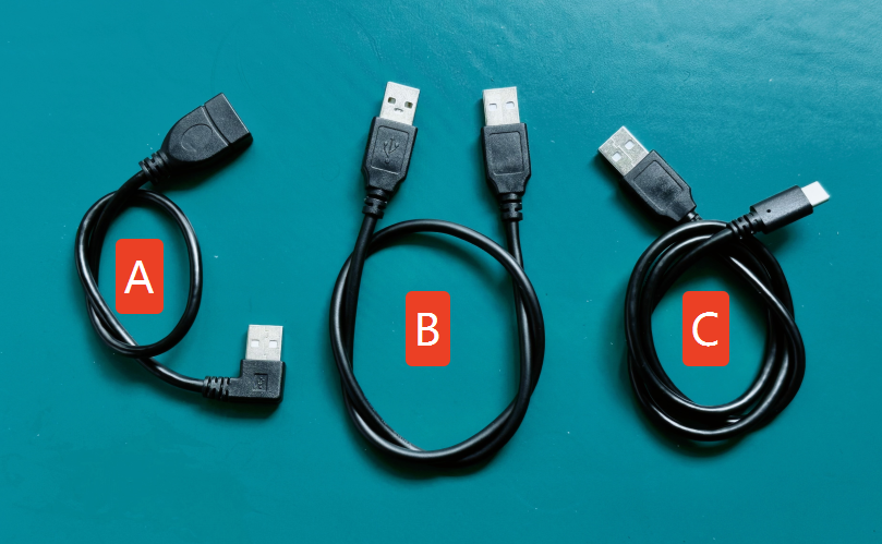
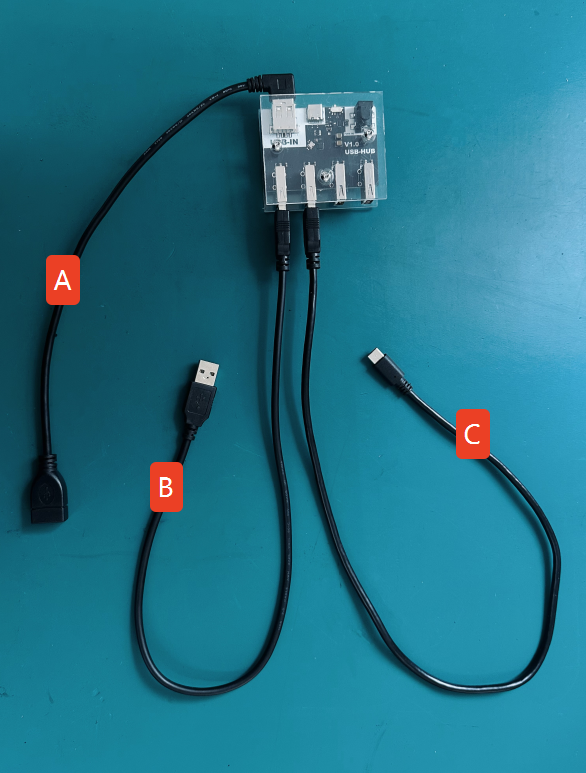
Prepare a data cable that can convert the Type-C male connector to a USB-A male connector.
Prepare a data cable that can convert the USB-A male connector to another USB-A male connector.
Prepare a data cable that can convert the USB-A female connector to a USB-A male connector.
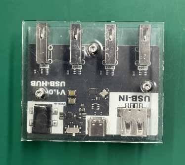
HUB Explanation
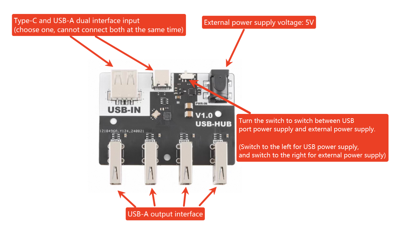
Prepare a USB Hub.
2.Download the calibration configuration file from the link.
————Mega Configuration.lbdev————
For MEGA firmware version 1.0.6.3 or above, please set the connection baud rate of Lightburn to 230400. For versions below 1.0.6.3, set the baud rate to 1000000 for connection.
For MEGAS firmware version 1.0.1.3 or above, please set the connection baud rate of Lightburn to 230400. For versions below 1.0.1.3, set the baud rate to 1000000 for connection.
3.You can operate according to the video or the accompanying pictures and text below.
¶ 2.Remove the side cover
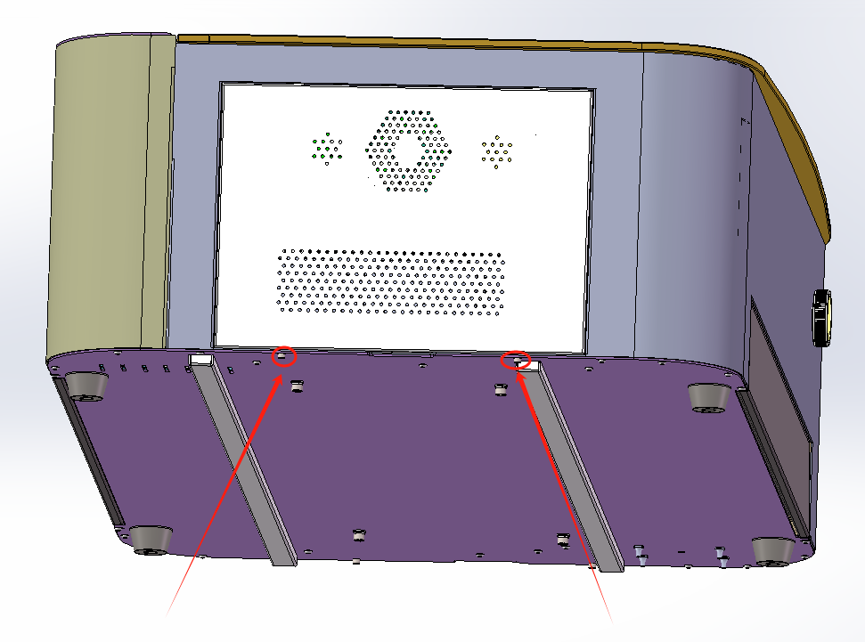
1.First, unscrew the two screws on the left door and remove the left side of the machine's door.
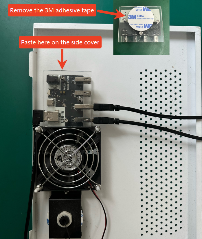
2.As shown in the figure, connect 3 data cables to the USB hub.
¶ 3.Modify the wiring of the camera
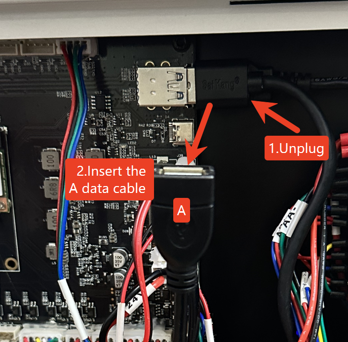
1.Remove the USB extension cable of the machine from the motherboard and connect the A data cable.
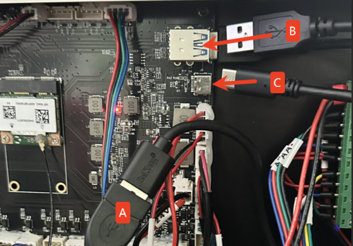
2. Connect the B data cable and the C data cable to the positions shown in the following diagram.
3.Remove the adhesive tape from the USB Hub and stick it onto the side cover as shown in the picture.
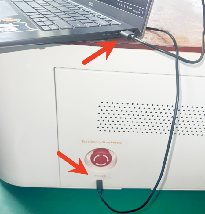
4.After the machine has completed its startup, connect the device to the computer using a USB data cable, and then open LightBurn.
Note:
After the renovation is completed, you need to turn on the device and wait for it to automatically complete the startup process. Then, connect the device using your USB data cable.
It is not supported to repeatedly plug and unplug the device for reconnection after a successful connection. It is not supported to insert the USB data connection device into the machine first and then turn on the device.
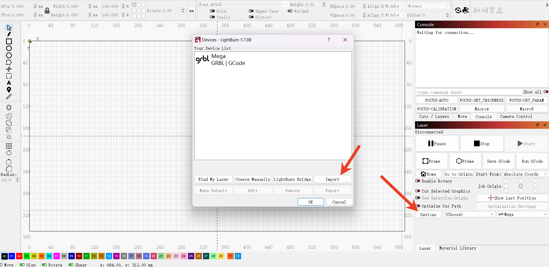
¶ 2.Import configuration file
Drag the file to any position in the Lightburn window or click "Devices" -> "import" to import it.
¶ 3.Calibrate the alignment of the camera
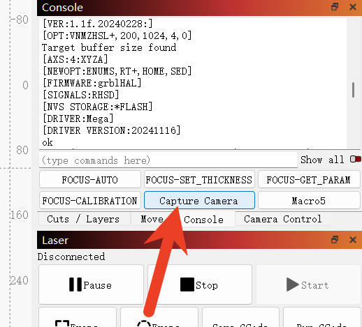
1)Click "Capture Camera" to capture the camera image.
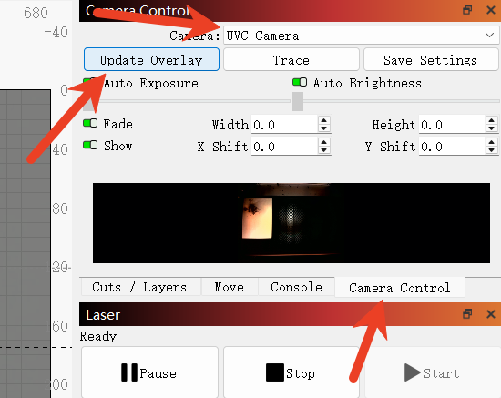
2)Select the camera and add the camera image to the canvas.
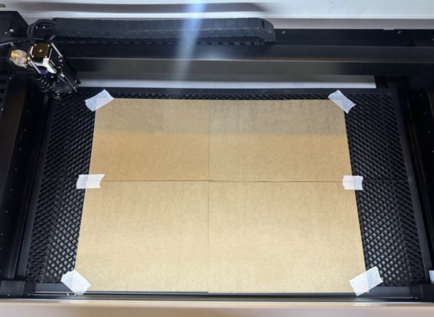
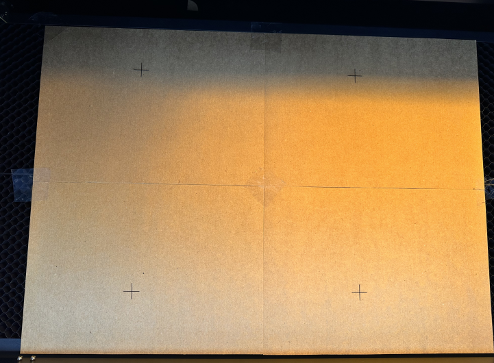
¶ 1.Place the carving materials
Prepare four wooden boards or four sheets of kraft paper and place them on the honeycomb board.
It is recommended to use the material you usually use for carving for calibration.
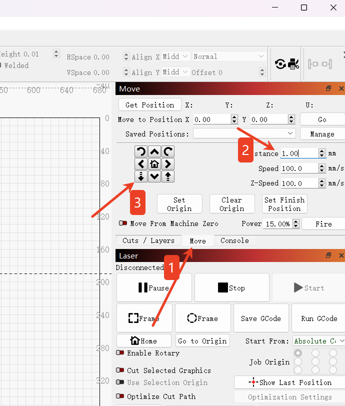
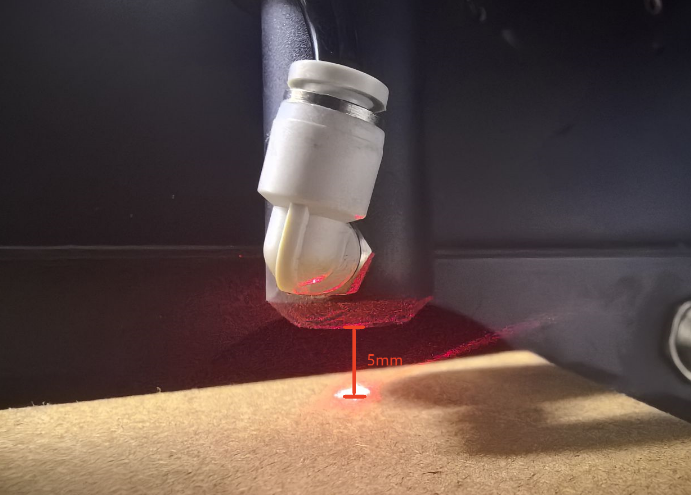
¶ 2. Adjust the height of the Z-axis to achieve focusing.
During the process of marking points, in order to achieve better clarity and accuracy, it is necessary to lower the Z-axis height by 5mm to ensure that the distance between the marking material and the laser head's light emission position is 5mm.
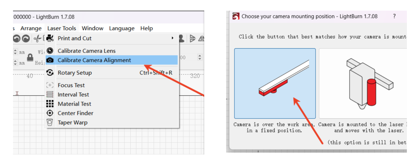
¶ 3.Select the cameras that need to be calibrated and aligned.
Click on the "Laser Tool" in the menu bar -- then click on "Calibrate Camera Alignment" -- select the "Fixed Camera" option on the left, and choose your camera.
.jpg)
¶ 4.Carving marking points
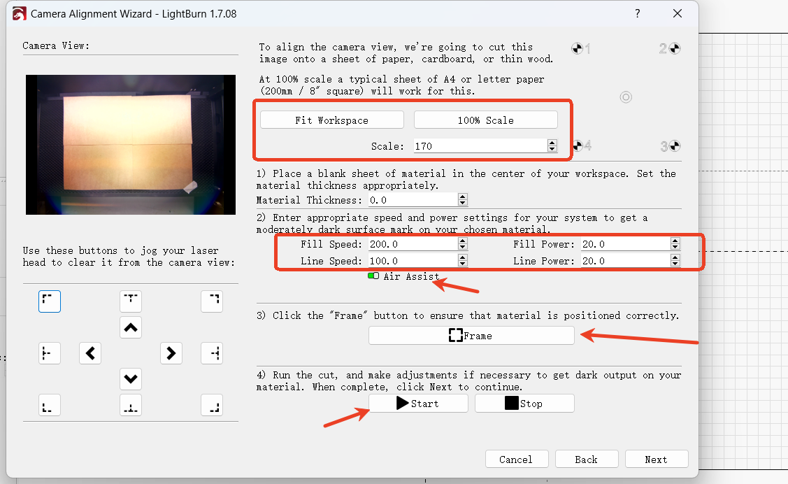
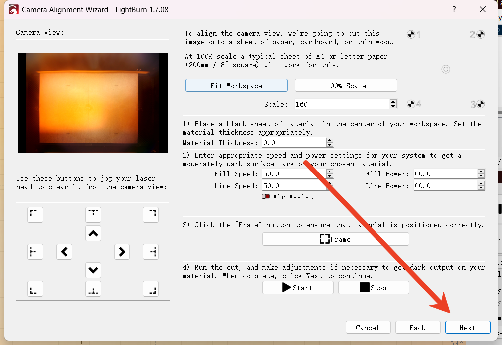
Step 1
Place the material at the center of the laser working area -> Set the proportion scaling, and it can also automatically adapt to the working space -> You can click on the border of the third step to preview the range. To achieve the best effect, please increase the Scale (scaling) value to the maximum amount that you can adjust.
Step 2
Enter the appropriate Speed and Power settings. These settings may vary depending on the materials used. The power can be adjusted from low to high to achieve the best carving without burning through. Therefore, we are unable to provide these for you.
Step 3
Preview the border for the pattern layout to ensure it is placed on the material you are using.
Step 4
Start the carving process. If the color is not dark enough, you can adjust the settings and run it again to make the pattern clearly visible and easy to observe. After the carving is completed, please keep the position of the carving material unchanged and click "cancel" to close the window.
Step 5
Go to the console window, click the "Capture Camera" macro button, and refresh the camera image.
Step 6
After the camera image has been refreshed, re-enter this interface and simply click "Next" directly.
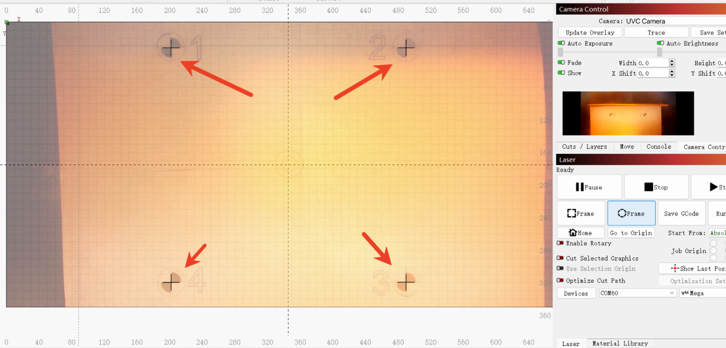
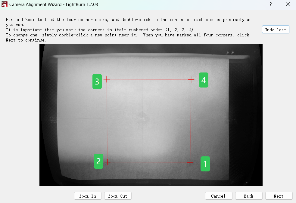
¶ 5.Mark the center of the target
Make sure that the captured image is clean and without distortion.
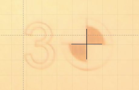
In this step, each target needs to be marked by double-clicking its center in sequence. You can also use zooming in and out to help you mark more accurately.
When double-clicked, a red "+" mark will appear. Place the labels in numerical order (1, 2, 3, 4) at the center of the four targets. If an error is made, you can double-click near it to move it, or click "Undo Last" to delete it and try again.
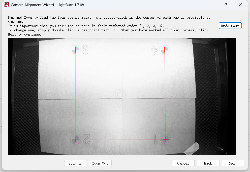
After completion, click "Next" and then click "Finish" to store your calibration results.
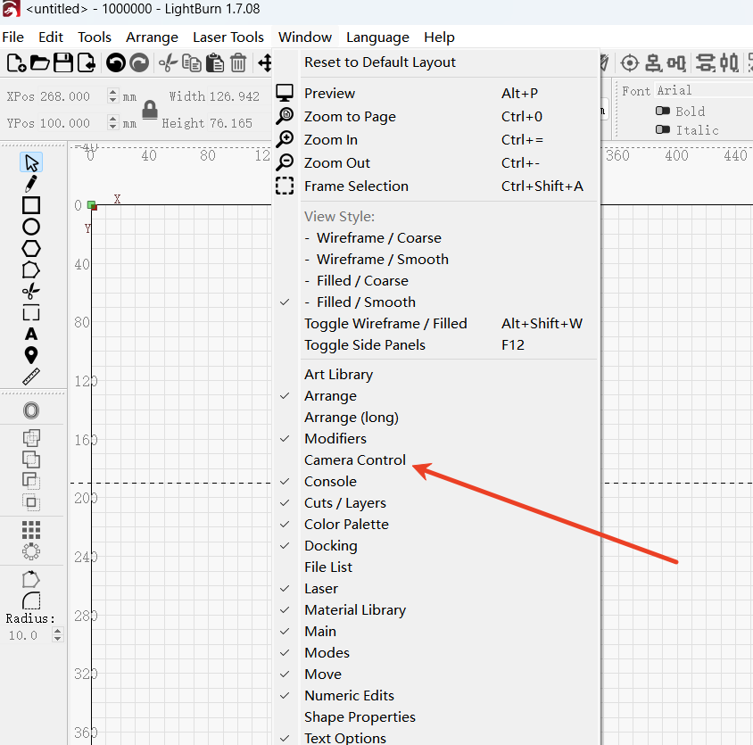
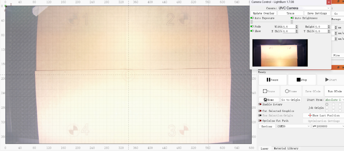
¶ 6.Add the camera image to the canvas
Click on the menu bar and select "Window" to check the "Camera Control" option.
Select the camera and click "Update Overwrite" to update the camera image onto the canvas.
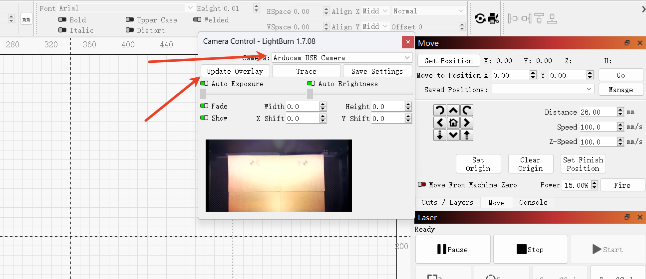
Congratulations! You have completed all the settings for camera calibration.
¶ 4.When there is an error in aligning the camera with the canvas, the solution is...
1.When you encounter the following errors, you can solve them by calibrating the camera alignment and modifying the positions of the marking points.
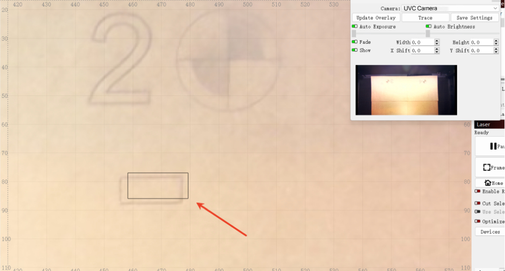
2. During the recalibration process, it is essential to ensure that the position of the material remains unchanged.
Manually add cross lines at the four positions on the canvas.
Align the cross as closely as possible to the center of the previous engraving.
3. After adding the cross lines at the four corners, the carving material should be reversed or a new material should be used for carving.
4. Go back to "Calibrate Camera Alignment", and then skip the sculpting step.
5. Then, in this order, edit the center points of the four cross lines. Once completed, click "Next" to save the calibration results.
If you still have any questions, you can refer to the calibration tutorial of "LightBurn" or contact the LightBurn customer service.
LightBurn Calibration Camera Lens Connection
LightBurn calibration of camera alignment link
LightBurn Software Forum - LightBurn support community
¶ 5.If you still have any doubts, please contact us.
Support Email: support@monportlaser.com
Mega After-Sales Number: +1 303 210 9328
WhatsApp: https://chat.whatsapp.com/GTTrZQ0FqKv9Ex58vq8ZXw
WhatsApp QR code:

Facebook Official Group: